Build Notes
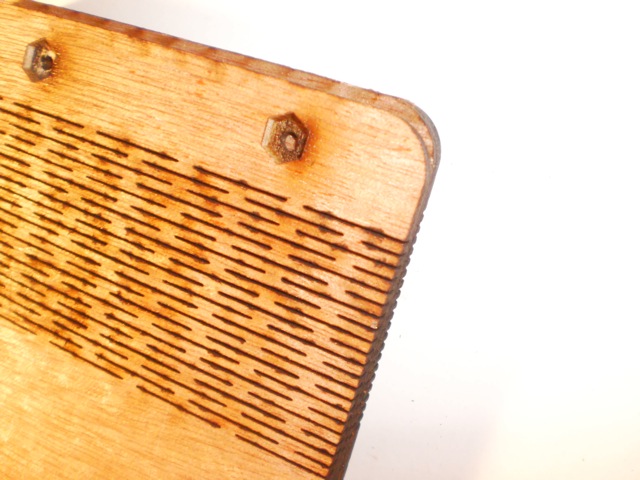
Troy gave me the idea for the hinges. These were done 2mm apart, as a single cut line on the cutter, i.e., the width of the slots is the width of the kerf of the cutter. Originally, I had designed a hinge where the slots were actually ovals, about 1.75mm wide. This gave me precise control over the width of the slot – but doubled cutting time. Between the slots and the engraving, we wanted to get the time per piece down to less than 40 minutes. I also tended to get embering and flareups on the hinges w/more material removed. Certainly setting cut order element by element would prevent that, by allowing the wood to cool down before a neighboring slot is cut.
The kerf at the bottom side of the cut is narrower, so I brought the speed way down to cut the slots cleanly on both sides in one pass. Details about power settings are at the bottom of this post.
The wood material is the 24“ x 24” luanne brand plywood we all know and love that Lowe's sells for $2.98. The hardware is 4-40 x 5/8 machine screws and nuts.
These were engraved double-sided by locking the raw material into the cutter and engraving and cutting the fronts sides completely. The pieces were then flipped within their cut outlines and the back sides engraved. This gives you relative registration within the kerf of the cutter, so say, 1-2mm, and presuming you can “register” your second file (for the backs) with the fronts.
This is made much easier by manually placing a tiny element in the art at far lower left. This element should be completely outside the “box” that might otherwise enclose all the elements of your art.
All vector software (like Adobe Illustrator, CorelDraw, LaserCut) rely on enclosing everything within a “box” and then grabbing the lower left corner as the master reference point. Technically, it's called the bounding box (i.e. the “bounds” of the total artwork), and the lower left is always the origin point, just like in Cartesian geometry.
This origin point of the bounding box is the blue dot/circle that shows the “home” location in LaserCut. By manually placing an element at the lower left of your art that is not part of the final piece, you force that home origin point to be in the same place every time.
For this project, the front and back version of the file both have that same reference element. It's the left-most, lower-most element. By definition, LaserCut will “home” on it. It's actually a 1mm circle, and I set that as the first cut layer, so I can actually see prior the start of cutting if the piece is “homed”.
The art was created in Adobe Illustrator, organized as layers for cutting/engraving. The native art file was exported as Illustrator 7 (which can be imported directly by LaserCut) with images embedded and all typefaces converted to outlines.
Images were prepped in Adobe PhotoShop. Generally, I convert source material to grayscale, where I'll perform aggressive color corrections to bring out the details that might suitable for engraving. This grayscale version is then converted to bitmap, usually in the 600-1200dpi range. Depending on the nature of the image I may allow a dither or mezzotint into the bitmap conversion to simulate “tone”. However, I've only seen that kind of detail show up if engraving in material that shows detail very well (fine grain hardwood or acrylic) and if you really commit to the time it takes to engrave at scanlines upward of 600dpi.
Cutting was done in six layers, in this order. The reason for cutting the slots and engraving last is those take the longest, and this way I could see if the rest was OK before committing to possibly trashing the material. The art and text would have looked better had I gone to a higher scanline, but again, that would have driven the engraving time through the roof.
Settings are shown in speed/power:
- 1mm reference circle - cut - s7/p100 (any faster results in no hole)
- (front only) bolt head countersink - engrave - s145/p90 - scanline 200dpi
- (back only) hex nut recesses - engrave - s135/p100 - scanline 200dpi
- bolt holes for spine - cut - 10.1/100
- art and text - engrave - s340/p40 - scanline 300dpi
- hinge slots - cut - s7/p100
- final piece outline - cut - 10.1/100
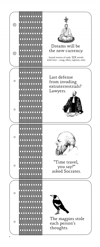
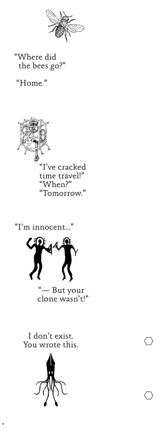
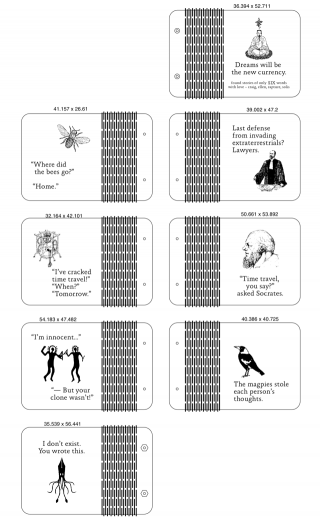
The three images below show the exported front/back files and the “working” master art. The reference point is the tiny 1mm circle at lower left of both pieces. I tried to upload a PDF with the vector art, but the wiki wouldn't let me upload a pdf (??).
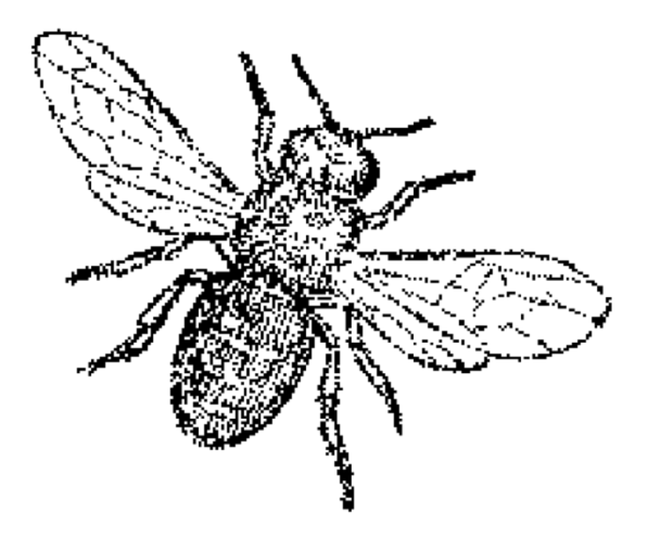
The fly image used in the actual project isn't really this low-rez, but this is what it looks like post-conversion, (especially to the engraver!). You can see in the body where the original grayscale tone translated to a stochastic pattern that is still just black or white pixels only.

