This is an old revision of the document!
Table of Contents
Laser Operations
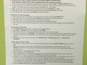
If you like the “how-to” small posters on the laser cutter room walls, you can download that PDF here.
Operating the laser is a rewarding experience, however it takes patience and training in order to do so safely and effectively. The guide below is intended to be a supportive utility beyond the required training to operate the equipment. Laser operation generally consists of preparing the material, preparing your cut on the computer using a CAD/CAM software toolchain, and finally, preparing and operating the laser cutting machine.
Before doing anything, read all of the posted safety and operational signage.
Material Preparation
Acceptable Materials
Approved materials are:
- non-treated woods
- acrylic
- cardboard
- paper
- glass (engraving/frosting only)
You are welcome to cut materials 3/8“ or thinner. 3/8” is “thick” for our laser. Feel free to touch base with the trainers if you are interested in cutting thicker materials.
Some not Explicitly approved materials, but have been tested to be ok, check with the laser officer before doing more than small samples of these.
- Speedball Speedy-Cut-Easy (the easy is important, non easy has pvc in it), other hackerspaces/laser users have reported using it fine
- Ingredients COMPOSITION / INFORMATION ON INGREDIENTS
Blend of paraphinic plasticizer, calcium carbonate, titanium dioxide, styrene butadiene styrene synthetic
rubber, white factis synthetic rubber, polysiloxane, magnesium stearate, calcium stearate. - It is a bit stinky.
- 3M™ Scotchlite™ Reflective tape, still unknown on composition of backing, but the tape itself is acrylic and the reflective stuff does not hurt the cutter, but does need to be masked with tape for good /clean cutting
Disallowed materials are:
- plastics prefixed with “poly”, e.g. PVC.
- treated woods
There may be exceptions. Again, talk to one of the laser trainers first.
Material Constraints
The laser operates on a 900mm x 600mm table. We don't recommend exceeding 800mm x 500mm1) in your design. Your material should be very flat. A non-flat material will result in imperfect cuts, both in desired shape and inability to punch your design out of the material blank.
CAD & CAM Operation
Designing Your Cut Files
Most vector drawing applications will be able to export into .dxf, the output file needed for our CAM program. Typical programs to draw your cut in are:
- Inkscape (free, open-source)
- Adobe Illustrator
- AutoCAD
- Creo/ProE/SolidWorks/Rhino
We use Inkscape, and have it ready on our machine. How to use Inkscape to generate “paths” will not be covered here.
Some members use Sketchup for their design work, instead of Inkscape. You must have a dxf export plugin to enable .DXF export. That plugin is verified to work with Sketchup 82) , unknown if it works with newer versions.
Work Piece Setup and Calibration
Work Piece Bracing
- Open the laser cabinet
- Insert your work piece onto the honeycomb bed
- Ensure that your work piece is flat on the surface.
- If your piece is not entirely flat, you may consider applying magnets to the workpiece to brace, lift, or flatten it. Do NOT place magnets in the laser path. Always assert that magets are placed OUTSIDE of the permiter drawn by the laser “Test” operation.
Use magnets and spacers as needed to align, flatten, or shim your workpiece.
Laser Focus Calibration
The laser should be focused to your workpiece on every cut.
- Grab the focus tool from it's very special home on the top, right surface of the laser.
- Lower the Z stage until there is a large enough gap between your work piece and the focus plunger (on the laser head) for the focus tool to fit in between.
- Press Z > DOWN-ARROW to lower the stage from the control panel
- Slide the focus tool between your work piece and the focus plunger.
- Ensure that only the plunger will make contact with the block as we anticipate the Z stage moving upwards. Take extra precaution to ensure that the block is not in the laser path (e.g. not in the same path as the laser head). Also, avoid plunging into the “FOCUS TOOL” lettering.
- While still in the Z menu, press “DATUM”.
- After the Z stage stops moving, remove the focus tool block by carefully sliding it out from above your work piece.
As with all tools, always return the Focus Tool to its home!
(need focusing procedure support imagery)
Go Time
It's almost time to cut!
- Move the laser to the origin of your cut.
- Hopefully, you set a reasonable origin when prepping your file in the CAM software. Generally, the origin is set to the bottom left of a virtual square drawn around your design. If you don't know with certainty where your origin is, go check now.
- Place your left hand pointer finger near the “Stop” button, and your right hand over the “Test” button.
- You will press “Test” and observe the laser traverse the outline of your design. If laser head exceeds the boundaries of your expected design and you fear that it will hit any of the limits of its availabel travel, hit stop immediately!
- Press “Test”
- Now you're ready. Read through the pre-flight checklist one last time, then press “Start”.
Pre-flight checklist
- Watch over your print. You are required to be present in front of laser during all cuts. Enjoy!


